New research project for Arnold Ravensburg on deburring with the laser tool.
(Funded by the Federal Ministry of Education and Research)
Objective of the R&D project
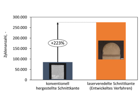
A large number of the installed chassis components are made from: high-strength sheet steel manufactured. Their performance depends largely on the behavior of the material under cyclic stress. Fatigue strength is therefore crucial; cracks often start from cut edges (Figure 1, left), which underlines the particular importance of edge quality for component integrity.

Established post-processing processes for deburring sheet metal are complex, subject to tool wear, usually require subsequent component cleaning and only solve the major problem of edge crack sensitivity inadequately and not in a process-stable manner.
Innovative solution approach – Special feature compared to the state of the art
A innovative, resource-saving approach for automated deburring and post-processing while simultaneously reducing the risk of edge cracks when using components laser-based edge finishing This is a non-contact and material redistribution process without material removal.
After cutting, the edges of the sheet metal components are melted using laser radiation. In the liquid state, the roughness of the edge can flow out due to surface tension and is smoothed. By appropriately choosing the process parameters, a defined rounding of the edge can be achieved, including edge reinforcement (Figure 2, middle).

At the same time, a heat treatment takes place in the area of the edge and the structure in the edge area is characterized by a gradient-shaped phase and grain distribution.
Result from the laser used neither tool wear nor grinding waste.
Subsequent Cleaning steps are no longer necessary complete.
High process speeds > 10 m/min almost regardless of the complexity of the edge geometry are possible.
This is to refine complex 3D sheet metal edges with the laser and thus qualify or establish the process for the broad market overarching goal of the DeLight project, to develop a machine with edge tracking for online correction of laser processing paths and dynamic inert gas guidance, as well as to validate the machine and process on end users' 3D sheet metal components.